What Controls a Motor?
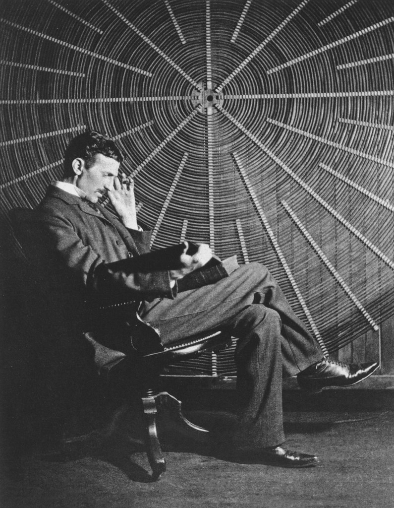
In 1887 Nikola Tesla invented an alternating current (AC) Motor to harness the power of electricity. It is a great invention but not as useful unless operators could turn the motor on and off. Therefore the “knife switch” was created, which connected the power to the motor when the operator manually pulled the switch to the “on” position.
It wasn’t long before they discovered this external switch is incredibly dangerous. Arcs would form at the contacts when operators closed the switch. The sparks from the arcs are a huge hazard that could potentially injure the operators. To prevent injuries, they placed the switch inside of an enclosure and put a handle on the outside. Now the electrical arcs are inside the enclosure and the operators were able to safely turn the switch on and off. The only problem with this is efficiency. So in order to power up multiple motors at once, they created a contactor.
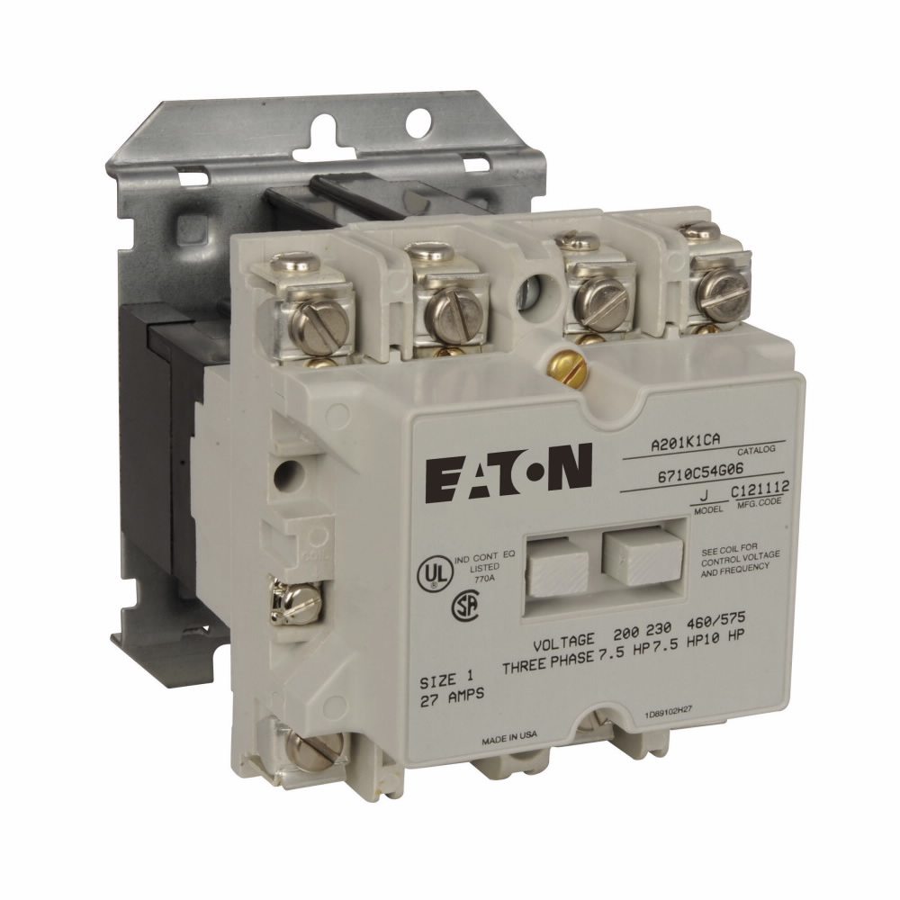
Contactors are able to turn motors on and off with a push of a button to remotely power up multiple motors at a time.
How Does a Contactor Work?
Inside a Contactor is a piece of metal with a coil of wire (usually copper) wrapped around the metal. Above this metal-coil wire is another piece of metal that is attached to an electrical bridge, known as the “armature”. The armature connects to the electrical contacts on both ends inside of a contactor. When an electrical current goes into the contactor via one of the contact ends, the coil charges up and turns the bottom metal into a magnet (electromagnet). This electromagnet attracts the top metal towards it, which in turn pulls down the armature attached to the top metal. The armature then closes the contacts on both ends. Once the contacts close, electric current is able to pass through the complete circuit. This in turn can power a single or multiple motors depending on the power of your contactor.
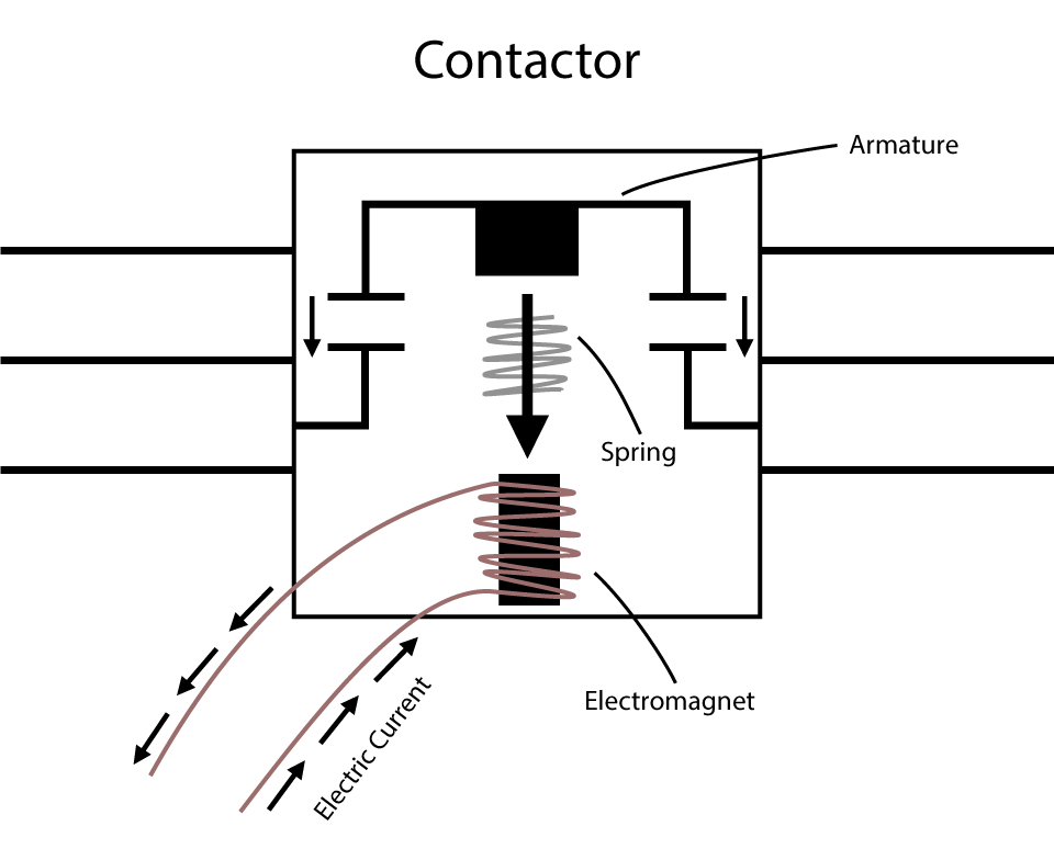
One thing to mention is that there is a spring sitting in between the top and bottom metals. Again, when the power is on, the bottom metal attracts the top metal. When this happens, the spring located in between the metals gets overloaded and overpowered, thus creating the electrical connection. However, when the power is off and the bottom metal ceases to become an electromagnet that attracts the top metal, the spring releases pressure by pushing apart the metals. This breaks the connection. As you can see, a control station can easily and instantly turn the coil on and off with electricity to remotely operate contactors thereby controlling many motors at once.
Extra Feature of a Contactor
While contactors are impressive on their own, an added auxiliary contact can make things even more interesting. An auxiliary contact usually mounts on the side of a contactor. A contactor has a piece of its armature sticking out to the side where an auxiliary contact could be hooked up. This allows the contacts inside the auxiliary contact to turn on and off when the contactor turns on and off. Auxiliary contacts could be “Normally Open” (N.O.) or “Normally Close” (N.C.) meaning their contacts could be off (open – not touching) or already on (close – touching) before hooking it up to a contactor. The great thing about an auxiliary contact is its ability to connect to another circuit.

Motor Control Hazards
The hazards that come with motors are short circuits and overload / overcurrent.
A short circuit can be caused by two things:
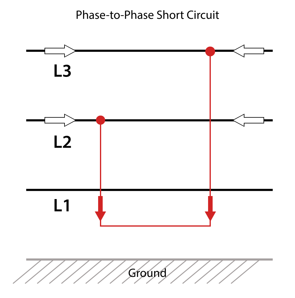
Phase to Phase Short
This is when one phase goes into another (two phases with no insulation accidentally touch each other). They create an unrestricted path for current to flow and a huge amount of current goes through them very quickly. This heats up the wire and burns down the insulation. Needless to say, the heat burning down the insulation can potentially cause fire.
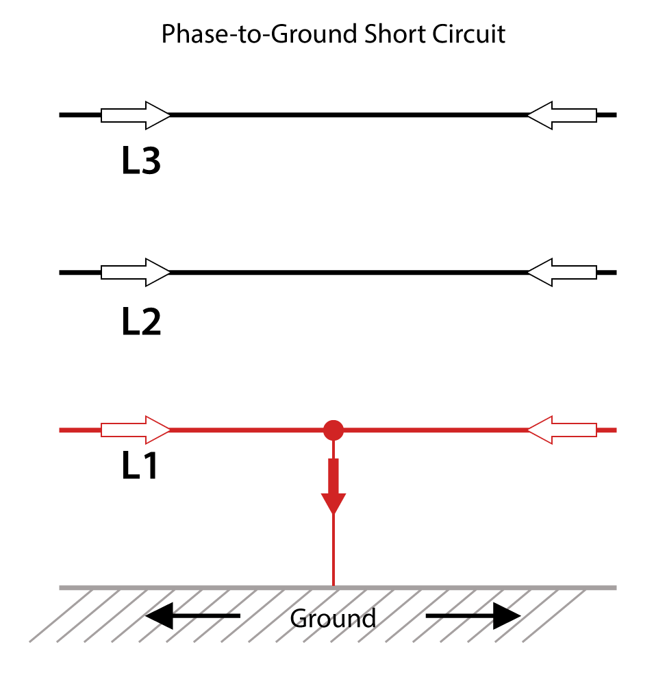
Phase to Ground Short
This is when a phased wire unintentionally touches a ground phase, such as a metal rail in a garage. This creates a path to ground from the phased wire. Again, the same problem occurs as the phase to phase short and can potentially cause fire.
The other hazard that could occur is a motor overload / overcurrent
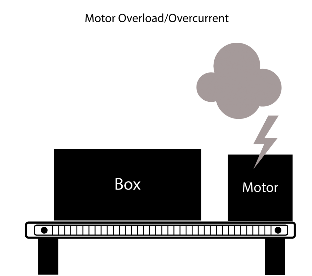
Motor Overload / Overcurrent
A motor overload / overcurrent is when the motor draws too much current. Motors have specific speed, load capacity, and current ratings. The motor will eventually overheat if it draws more current that its normal rating range.
Motor Control Hazards Protection
So how do we protect motors from these harmful hazards? A popular and most common way to protect a motor is by using a molded case circuit breaker. This is due to the fact that the breaker has two different circuit protection inside. One is magnetic, which protects against short circuits. The other is bi-metallic thermal circuit protection, which protects against overload / overcurrent.
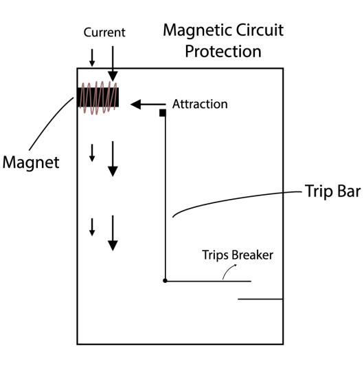
Magnetic Circuit Protection
This type of protection protects against short circuits. Similar to a contractor, the inside of a molded circuit breaker also has a coil of wire wrapped around a metal core. Next to the coil of wire is a “trip bar” that trips the breaker to prevent a short. The wire coil magnetizes when current passes through the breaker. When a huge amount of current goes through the coil of wire, it creates a strong magnet that attracts the trip bar towards it which causes the circuit breaker to trip.
Note: Magnetic protection is great for protecting against short circuits because it reacts to a very high amount of current very quickly.

Bi-metallic Thermal Circuit Protection
This type of protection protects against overload/overcurrent. There are two thin strips of metal bonded together (bi-metal) and a trip bar next to it. Here’s a little theory: we know that metal expands when it gets warm. So if we have two different types of metal bonded together, it’s likely that one side will expand faster than the other. Therefore the whole strip of metal will bend if the one side expands enough. As we pass current through the bi-metal strip, it starts to heat up from the current. If the current becomes too great, it bends towards the trip bar until it finally trips the circuit breaker.
Note: Bi-metallic thermal protection is a slower reacting protection. It correlates to the amp rating you see on the front of the circuit breaker. This is to prevent against overcurrent.
Molded case circuit breakers don’t know exactly what devices they’re protecting, so they protect the wires that feed these devices instead. If the breaker senses too much current going through those wires, it trips and allows the wires to cool down.
Electric Motor – Inrush and Full Load Amps
The problem with molded case circuit breakers’ thermal protection lies with the amount of current it takes to turn on a motor. To get a motor up and running from a dead stop, a huge rush of current must occur at the very beginning. After this rush of current, the motor levels out and runs at about a 100% speed. At 100% speed, the motor will pull a certain amount of continuous current until the operator turns the motor off. This current at 100% full speed is called “Full Load Amps” (FLA). The big rush of current at the beginning is the “Inrush” current and is usually about 6-8 times the FLA of the motor.
So back to the thermal protection problem in molded case circuit breakers. You can imagine how the Inrush looks like an overcurrent condition to the molded case breaker. Remember, the breaker is designed for short circuits and overload conditions but not specifically designed for motor protection. When the breaker sees the large draw of current, it trips to protect the circuit. This is problematic because the motor needs that Inrush to start running, otherwise it won’t be able to start at all. However, there is a specific type of molded case circuit breaker where the thermal protection has been removed. This type of breaker is a Motor Circuit Protector and is great for overload/overcurrent protection in motors.

Motor Circuit Protector (MCP) & Motor Control Setup
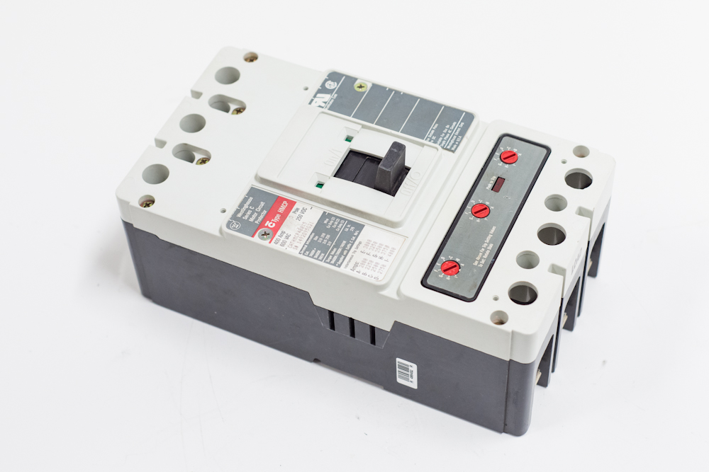
This type of protection does not have thermal protection in order to ignore the Inrush in motors. Eaton has a nice line of High-Interrupting Motor Circuit Protector (HMCP) circuit breakers. However, without thermal protection from overload/overcurrent conditions, the breaker still needs a way to protect the motor from overcurrent. To do this, we would need to combine a contactor with an overload relay. In this setup, a contactor has power coming in from the top and coming out at the bottom. Below the contactor is an overload relay, which receives power at the top from the contactor. The overload relay has 3 bi-metal strips inside that heat up at the same rate as the windings of the motor. This is different from the bi-metals inside the breaker because those bi-metals did not know to ignore the Inrush when a motor starts. When you pair a contactor with an overload relay, it is called a Starter or Motor Starter.
Now to complete the motor control setup, we need the MCP (or HMCP) at the very top to provide a way to disconnect the entire circuit from power. It will also provide short circuit protection since it still has the magnetic protection inside. Next is the starter (contactor + overload relay). The Contactor provides a means of controlling the motor while the overload relay protects the motor from overload conditions. This whole setup connects and powers the motor (or multiple motors).
